
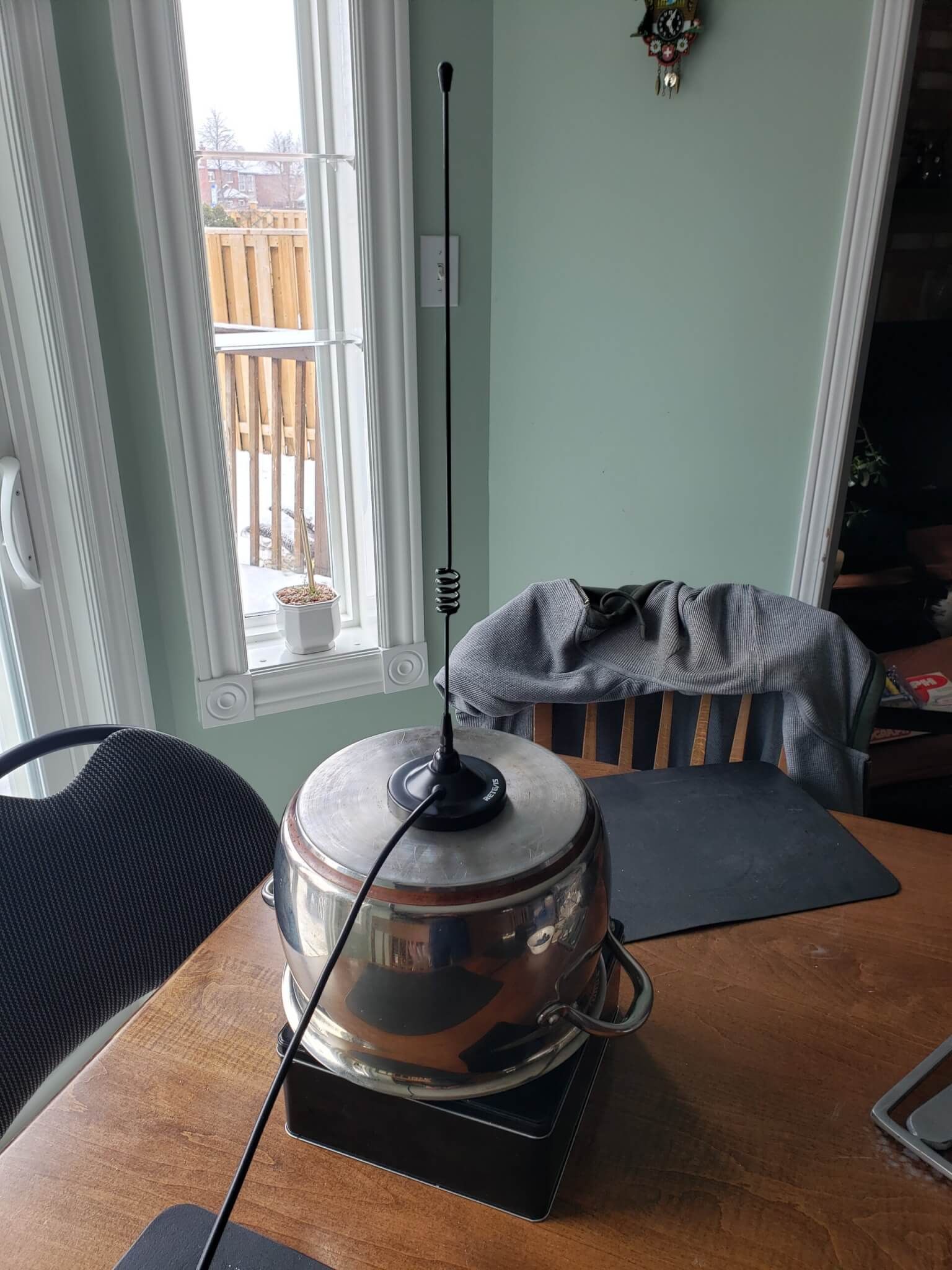
The Great Canadian Antenna

Can it get anymore Canadian than this?

Long-time members and readers may remember the Great Canadian Alligator Clip and how we put it to good use keeping some librarians nicely grounded.

What could we do for a patriotic encore?

The answer came to us from ylab friend John/VE3IPS. We were storing some old radios in a shed, and sent him this picture.

John’s reply: “Luv the snow shoe antenna….40m is open. Work some”

40 metre? At that length? John may be the McGyver of antennas, but in this case, he’s out of his mind… in a different way than he’s usually out of his mind,

Nevertheless, challenge accepted.

A quick measurement of the length, a basic calculation, and we figured that the pair was not to far from the ideal length for a 6 metre dipole.

The tails of the snowshoes are hollow, and just a bit smaller than a half-inch bolts diameter. Perfect. The magnesium is so soft that with just a bit of torque, the bolts nicely tap themselves in.

From there, strip some coax and tie in the ends of both shoes

Now bolt the shoes to a stand.

, and we have something that looks… nah, I can’t call this reasonable.

We hooked it up to our handy little nanoVNA, and it gave us an initial SWR of 4.4. But that’s down in the basement, too close to other metal object. Tighten the connectors, a bit more jiggery-pokery of the cables, better location and we got it down to 2.3. Best result, as predicted, is on the 6 metre band.

Another radio friend John/VE3BOF brought in a more expensive SWR meter and confirmed the 2.3 measurement. And being the nice guy he is, he also brought in a radio that supports 6 metre.

We put the antenna outside on a cold snowy evening and to try it out. Sloth, expediency and the lack of a decent extension cable kept the antenna pretty close to ground level.

The results? We were receiving!

Transmitting was another matter. By dumb luck, VE3NRT was on a 6 metre net, operating from about 20 km away. With some repetition, he was able to hear us and make out what we were saying.

We’re guessing the shape of the antenna, what with all the holes and different paths to the tip, made transmitting a bit of a disaster.

Would a higher location make a difference? That research will have to wait until spring. If you look at the bottom right of that last picture, there’s some white stuff on the ground. Those snowshoes are going back to their original use.

Bottom line: if you want an emergency antenna, pack a roll of wire. You’ll dramatically increase your chance of rescue. Unless, of course, you’re in an area where a good pair of snowshoes would help you trudge out of there.

Antenna science goes to pot

Half-baked or well done?

If you know anything about radio and antennas – and if you don’t, check out our beginner radio and antenna pages – you know that the most basic antenna is a dipole, and a dipole antenna has two sides. All antennas require two sides.

A magnetic mount antenna (magmount) looks like it has only one side. That’s because the other side is the car. Really.

So if you want to use it as an antenna in your house or somewhere else… or if you don’t own a car… or you don’t want to drive your car into the second floor of your house to get that height advantage (it’s been done), what do you do?

The answer from most hams is to put it on a cookie sheet. Not an aluminum cookie sheet, because the magnet (that’s the mag- part of mag-mount) won’t stick to it. That metal you attach the magmount to is known as a counterpoise.

So we thought… is the cookie sheet ideal? What if we got something with a heck of a lot more metal? Better magnetic properties? Science – and idle time under COVID lockdown – demands an answer.

To test, we are using a nanovna – that’s nano for it’s tiny size, and VNA for Vector Network Analyser. Sound expensive? For $50-$60 and it’s an incredible deal. Comparable units used to cost thousands of dollars.

We use the nanovna to measure the SWR – Standing Wave Ratio, the preferred measure of antenna efficiency. SWR of 1 is perfect – all the energy is going out as radio waves. Anything below 2 is generally acceptable when dealing with higher-power HF radios. Above 2, and you need an antenna tuner to compensate.

But first a few caveats:

  • There are a lot of cautions with nanovna, like the need to calibrate within the frequency range for the test. We’re not providing the details here because the nanovna documentation, beginner guides and forums are phenomenal. The cookie sheet vs other pots counterpoise assessments, on the other hand, are sorely lacking.
  • Our measurements are not lab-grade. Every stupid little thing can affect the SWR measurement. Wiggle the antenna wire and it changes. Stand next to it and it changes. Eat a cookie and it changes (we use our cookie sheets for their original design purpose). Formal testing involves setting stuff up in a field outside, fixing the wires, complex instrumentation and more. We didn’t do that.
  • Ground (as in dirt you are standing on) can be an effective counterpoise, or part of the counterpoise. Moving your cookie sheet from a table top to the ground can make a difference.
  • Our measurements are consistent relative to each other. We had some significant variance for the tests for many of the items tested. But from item to item, the variances were pretty consistent.

Baseline: no counterpoise

We started with the antenna on a table (SWR: around 8) , and then for consistency with other measurements, on a plastic case on the basement floor (SWR: around 6). Either way it sucks, but it seems that proximity to actual ground makes a difference.

Our choice of weaponry:

  • The classic cookie sheet
  • A cast iron frying pan
  • A large pot rated for induction cookers

The classic solution: a cookie sheet

The nanovna is tiny device – 15mm thick, but otherwise not much bigger than a credit card. There are bigger versions and people will tell you to spend more $ for them because they’re easier to read. But even then, capturing the screen would be a challenge. Why bother with the larger unit when there’s free software to display the data live on a PC?

SWR, because it’s related to impedance, varies with the frequency. For our tests did a rough scan of the VHF frequency range, from 144 MHz to 146 MHz. The graph shows the SWR ranging from about 1.7 at 144 MHz down to 1.43 at 146 MHz. The exact number for 4 data points are in the table immediately to the left of the graph. 1.43 to 1.7 – all well below the acceptable value of 2, and much better than the 6 to 8 of the antenna alone.

Heavy metal: 12″ cast iron frying pan.

This is one heavy sumofasumthin. You don’t lift it with one hand. And if you’re a cast-iron cooking fan – yes, it’s been properly seasoned.

We don’t have a picture of it with the antenna on it because we forgot to take the picture before we took the antenna off and there was no way we were going to put it back on. The magnet loves the cast iron. It doesn’t want to let go. We can’t even slide it on the pan surface. It took an assistant, profanity and prying with a screwdriver to get it off.

You can see the lovely scratches from the poking and prying.

As for the results… 1.734@144 MHz and 1.375@146 MHz. All in the same range as the cookie sheet.

Big induction pot (dutch oven)

This is a heavy pot – Costco’s own Kirkland brand. It’s not as heavy as the cast iron, but definitely heavier than any other pot we’ve seen of this size. It’s rated for induction cookers, so it’s got metal that responds well to magnets. The magnet definitely likes it, but not as much as the cast iron. We could slide it and get it off without drama.

The readings: 1.590@144MHz to 1.283@146 MHz.

Impressive. Less metal and less magnetic adherence than the cast iron, and less surface are than the cookie sheet, but better than both.

Combos

What the heck, we’ve got all the pots here… let’s try some stacking.

Cast iron and cookie sheet gave us 1.43@144MHz to our lowest-of-the-day 1.18@146 MHz.

The most surprising result was the induction pot on the cookie sheet. It’s worth showing the graph for that one.

Nice, flat 1.28@144MHz (lowest of the day) to 1.30@146 MHz.

Analysis and hypotheses

Mass of metal doesn’t seem to be a factor, since the cast iron pan didn’t do much better than the baking sheet. Our dutch oven did best, and it has a clear height advantage over the other two, and the height was further increased with the cookie sheet underneath. Small length differences make a difference for any antenna type.

So we need a few more tests to better differentiate between height, weight (quantity of metal) and magnetic attraction.

Next tests

We brought in a couple more items. We’ll only report the relative numbers, since the test conditions were different – i.e. we need some daylight once in a while and crawled back upstairs. (It’s OK. It’s my basement, not my mom’s).

Our additional test candidates:

  • A cookie tin that, on it’s side, is about the height of the dutch oven
  • A really tall aluminum turkey deep frying pot

The aluminum pot was useless. Magnet doesn’t stick to it, and high SWR. So the magnetic link is critical.

We tried the cookie tin lying flat and up on its side. On it’s side, the height is comparable to our dutch oven – and the results were comparable as well. When sitting flat, the results were not as good.

So:

  • Weight is not that important
  • Height is critical
  • Magnetic attraction is critical

And combos?

Cookie tin on top of the dutch oven gave us better results than either one alone. The relative results:

  • Vertical tin: 1.20@144MHz and 1.30@1.46 MHz
  • Dutch oven: 1.20@144 MHz and 1.24@146MHz
  • Both: 1.10@144MHz and oops-didn’t-write-it-down

So height seems to win the day,

More tests could be done. But we had to release the pots for supper preparation.

For completeness: we tried the dutch oven on top of the aluminum turkey pot to see if magnetic adhesion to the dutch oven and dutch oven contact to the aluminum would work. It didn’t.

Final conclusions

The ultimate reading is how well others read your signal. But before you start bothering other people, a nanovna is a great way to figure out how well thing are working, and, in particular, how they work in your particular setup. Simply moving from one place to another can affect things.

A cookie sheet is not the best solution – so if you don’t have on or only have an aluminum one, don’t go out and buy another one just for your radio.

Our fried VE3IPS says to stick the magmount on a file cabinet… but ours is in the basement. The test would be pointless. Your results may vary.

Big tall pot that sticks to magnet is the best starting option. Then work on combos.

The cookie tray goes back to the cupboard for now.

The cast iron frying pan and the other pot go back to what they do best.

Click for recipes for fried chicken or corn bread.

Yes, we did make this stuff. The maker movement isn’t just about technical stuff. Man does not live by tech alone.

Baofeng DM-X/DM-1702: Is this the saddest radio ever?

If only as a warning to others.

Way back in 1976, General Motors introduced the Chevette, a sad little cramped hatchback that, when equipped with the automatic transmission, could barely drag itself above 100 km/hour. Friends had rusted-out Pintos and Toyotas that we would rather ride in than a new Chevette. GM was the biggest automaker in the world. They had engineering resources in Europe and Asia that knew how to make small cars. There was no excuse for this sorry little atrocity. They should have known better. That’s how we feel about Baofeng and the DM-X / DM1702.

Yeah, we’re dumping on on this radio. If you have the misfortune of having bought one, keep reading because we provide a bunch of links and info to make it usable.

We really don’t want to dump on Baofeng. They make some great cheap radios. We’ve written an entire how-to guide on the UV-B6. It’s been a rugged little starter radio and we’ve recommended it to lots of people. Lots of cheap accessories. A Scout group we helped out with their ham certifications all have them, and they’re still going after two years and plenty of abuse.

With a goal of trying out one of the digital radio protocols for the first time, we ordered up a Baofeng DMX, which supports the DMR spec. It’s sometimes referred to as the DM-1702, and on their official web site, it’s the DM-1702B. These three are essentially the same radio but with different cases and button layouts.

The manual

This is the manual that came with the radio. The picture looks nothing like the radio we received. Front panel is different. Side buttons are in different locations. Pressing a side button provides a completely different function than what the manual says. Different… and we can’t figure out what it’s doing.

So we do some web searches. There is an official manual on the Baofeng web site, but… it’s a radio manual. They are never very good. The manual lists features that this radio doesn’t have. Like the flashlight.

Why do Baofengs have a built-in flashlight?

To help you find your good radio.

VFO mode… or not

OK, let’s try entering VFO mode (that’s ham-speak for “enter the frequency manually” mode, instead of using presets).

No combination of buttons will put the thing in VFO mode. It’s presets or nothing. A search of the manual shows that you can go through a few level of menus to enter a frequency and other parameters. This is usually only required for duplex/repeater setup.

Search the web… all you find is the sobbing of radio buyers crying out for a VFO function. It doesn’t seem to exist. You have to run through the menus. Top left button is Menu then Settings -> Program Radio -> RX Frequency.

Update: there are a couple of ways we’ve figured out to move from presets to VFO. That’s in the programming section below.

Keep going from that menu… enter RX (receive) and TX (transmit) and the CTCSS frequency for a local repeater and we’re good to go.

Hit the transmit button and…

Local interference

SWEET JUMPIN’ JEEBUS IN A FARADAY CAGE! WHAT’S THAT NOISE?

As soon as I hit the transmit button, the paper shredder behind me starts running. Try it again. Same thing. Consistent, repeatable test from up to 4 feet away. BUT THE SHREDDER HAS NO REMOTE CONTROL FEATURE!

This shredder has some kind of touchless sensor that detects when you insert a piece of paper. Must be triggering it somehow -maybe induced voltage on the sensor’s wire acting as an antenna?

I’ve tried it in a couple of other rooms around the house. It induces clicks and buzzes in a clock radio that isn’t even on.

I took off the included antenna and hooked it to the cable to the outdoor antenna. No interference. So whatever it is, it’s coming off of the antenna and not the circuit board. Switched to a whip antenna. Same interference, so it’s not a defective antenna.

Note to self: hook up the RTL-SDR and see what the splatter looks like.

Update: other radios have the same effect – so it appears it’s the shredder’s problem and not specifically the DMX’s fault.

True dual-tuner operation

Finally! Something positive to say!

It is a true dual-tuner radio and you can monitor two channels simultaneously.

One of the side buttons switches between the A and B frequencies. Punch in separate frequencies for A and B, and it is monitoring both simultaneously. Hitting the top-right Back button mutes and unmutes the second frequency.

Programming the radio

A quick check to see if Chirp supports the radio… and no luck.

Oh. Right. It’s a DMR radio. That means the dreaded code plug. Which requires software. Which was not included with the radio.

First try for software: contact Baofeng

It’s hard to find the real Baofeng company website because so many websites selling their radios falsely claim to be official Baofeng sites. With a little digging, we found these official company sites for Fujian Baofeng Electronic Co:

We put messages on all three asking where we could get programming software and firmware download for the radio.

Update: We got a message back from the corporate site, where we found the radio listed as the DM-1702B, which for download shows only a manual. They referred us to the page for the DM-1702, which contains the most recent version of the programming software V1.00.79 – with Chinese installation menus. After a few failed attempts – we had to guess which buttons are OK and Cancel in Chinese – we got it installed. It comes up in Chinese, but if you hit the button in the picture below, it switches to the English menus.

But… despite repeated requests… they don’t put the firmware updates on the website. Feel free to submit your own messages and up the pressure.

Second try: search the web

We found various forums, videos and Baofeng-selling radio sites that have a variety of firmware and programming software versions. Some claim that some of the releases had viruses and had to be cleaned up.

To make a long story short and save you some pain:

  • Programming software and firmware indicated for DMX or DM-1702 works.
  • Programming software for other Baofeng radios like the DM-1701 and DM-1716 does not work for this radio.
  • Programming software and firmware are often found together in a bundle.
  • The programming software is an executable called either CPS.exe or CPS2_extra_menus.exe.
    • The latest version we found is 1.00.78 Update: see above for link to the programming software on the Baofeng site. It has the extra menus.
    • The software seems to be specific to the radio model. The CPS.exe for other radios doesn’t work.
    • The _extra_menus software provides extra screens requiring a password. Best not to touch the values… but if you’re curious, the password is 66660501.
  • The firmware to download to the radio is in a file of the form fw_2.2.22-decrypted.zip. The version without decrypted in the name doesn’t seem to load.
    • Our radio shipped with 2.2.14
    • 2.2.22 is the most recent we’ve found
    • To display the firmware version: Menu -> Settings -> Radio Info -> Versions

We recommend upgrading to the latest software before configuring the radio. A few things were cleaned up since the earlier version.

Upgrading the firmware

This video provides instructions and links to download the software and firmware, and takes you through the entire process. If for some reason the links are missing, we saved a copy here with CPS 1.0.78 and firmware 2.2.22.

You will need a programming cable – and the good new is that any micro-USB cable will work. There is a cable from Baofeng that plugs into the mic jacks, but it’s not required.

The process is straightforward:

  • Download and start the CPS software
  • Turn off the radio and connect it to the PC with the USB cable
  • Hold down the # key while powering on the radio
  • From the CPS program, select Program -> Tool and pick your firmware

Note: Functions for loading/unloading configuration or firmware in the CPS software will pop up a window that looks like something is happening… but it sits there doing nothing. You have to hit the OK button to get things started.

Configuring/programming the radio from CPS

After starting the CPS program, you need to read the current configuration from the radio. Then all the screens are enabled.

Here are a few highlights.

It’s a good idea to save the configuration before making any changes. That way, you can restore it if you really mess it up.

Buttons

The most useful part of the CPS program is the ability to configure the three buttons – the two on the left side, under the transmit button, and one on the top, under the General Setting -> Buttons screen. The three buttons are identified on the screen as follows, wity our preferred settings for them:

  • Side-bottom (immediately under transmit): Middle
    • Short press: Up and Down Screen (for A/B switch)
    • Long press: VOX
  • Side-middle: Moni
    • Short press: Monitor (turns off squelch)
    • Long press: Adjust power level (low 1W or high 5W)
  • Top of the radio: Top
    • Short press: Scan
    • Long press: Battery power indicator

The P1, P2 and P3 buttons are not available on this radio.

There are a bunch of other functions that can be programmed on to the buttons. Just remember that many of them don’t exist on the radio.

Parameter, Menu and other CPS screens

Lots of different settings that you either can’t set from the radio, or that are easier to set on the screens. Have fun looking around.

Look on the Parameter page for things like enabling GPS and APRS.

DMR and station pre-sets

This is where things get a little hairier. We’re not going to get into a detailed explanation of DMR – a sort-of-standard for digital communication – because there is lots of good information elsewhere.

What you need to know: All channel presets on this radio – analog or digital/DMR – are tied to a DMR zone. If you are setting up analog simplex or duplex/repeater channels in the Channel menu of CPS, you must do the following or they won’t show up on your radio presets.

  1. Assign the channel to an RX Group List – do not leave the value as None
  2. . Assign the channel to a Zone on the Zone menu.

DMR Usage

We’re still working through this. Miklor’s page on the DM1702 says that you can’t monitor a digital talk group on a repeater. We’ve found that when connecting to a repeater, we are hearing whatever is on the channel.

What we have not been able to do is confirm DMR transmission from the DM-1702. Even connecting to the Parrot 9990 channel – it’s a test channel that repeats back what you transmit – we can’t get a response back.

But we are new to DMR, so maybe we’re making a mistake. Maybe it’s something to do with the local repeaters. The local club is heavily biased towards Fusion, a different digital radio spec.

Well keep working it.

VFO – with frequency display (no label/text)

In the CPS configuration program, after you have read in the config from your radio or from a file, you can go to General Settings -> Parameter. Near the bottom right corner, there’s a setting for Frequency/Channel Mode. If you set it to Frequency and update the radio… Yeah! You can enter the frequency manually!

To switch between VFO and preset mode, hold down the Back button (top right corner) for about 5 seconds.

Unfortunately, in this mode, presets are only displayed with the frequency. The name/label is not available.

VFO – with frequency label

This may be a blessing in disguise. The problem with VFO is that if you’re doing it with repeaters, entering the offset and CTCSS setting from the radios’ menus can be difficult.

The DMX makes it really easy to do from the settings screen.

So here’s how we handle VFO if we want names instead of the frequency displayed:

  • From the CPS menu, go to Channel -> __Channel
  • At the bottom of the list, add three channels
    • VFO3DMR
    • VFO2CT, channel type analog, with CTCSS
    • VFO1ANALOG, channel type analog, with no CTCSS

By doing it in this order, when you scroll back down from presets 3…2…1 you then hit your VFO channels. Don’t forget to assign the channels to Zones, or they won’t display.

To assign as frequency as if you were doing VFO:

  • Go to the preset you want to modify (one of the three we set up)
  • Menu (top left button)
    • Settings (might need to hit up or down arrow(
      • Program Radio
        • You are now making changes to the VFO channel you want to modify!
        • The menus make it easy to change each of the settings
        • The settings are appropriate to analog or digital based on the preset type
        • For the frequency, you will get a box with a frequency. Hit OK again to go to the edit screen. The top right button is now a backspace key, and you can use the numbers to enter your frequency. Hit OK when done.

I use a separate preset channel for CTCSS because if encode or decode settings are on for the channel you picked, you might forget about it, and you won’t be able to transmit or receive unless you clear them.

Sending DTMF tones

  • Be sure you are on an analog channel.
  • Press the # key (will have no effect if on digital channel)
  • Enter your tones.
    • Up/Down arrows: AB
    • Menu (Top left corner) button: C
    • Back (Top right corner) button: D
  • Press PTT to send

If you make a mistake and don’t want to send, there is no way to clear what you entered. Power the radio on and off. Seems dumb, but then again, on any other radio, the tones are sent as your press the keys.

Entering text

If you want to type in a message, enter a label, or whatever else that requires text, the behaviour is, at first… bizarre. You can enter a couple of characters, then Chinese characters start showing up. That’s a good thing if Chinese is what you want. As for the rest of us…

In the upper-right hand corner of the screen, you see the letters PY. That means the radio is set for Pynyin text entry, a method for entering Chinese characters using the western alphabet.

If you click the # key, you can see the PY change. It will cycle through four character sets:

  • PY: Pynyin
  • 123: Numbers
  • abc: Lower case letters, with the zero key as space
  • ABC: Upper case letters, with the zero key as space

For editing:

  • Up-arrow: cursor left
  • Down-arrow: cursor right
  • Back key(upper-right corner): backspace/delete

If you need spaces when entering numbers, you need to back-and-forth to the alphabet modes.

If all else fails…

This forum has been a great source of information and has an active community around this radio. One of the posters on the forum shares a google drive with firmware updates. Before using any of the updates, be sure to read through the forum for words of advice and caution.

When using the forum, you’ll notice a skinny vertical slider bar on the right of the window. Pull it down to the bottom to get the most recent posts and work your way back up.

The forum has a post we have not tested yet on configuring the radio for APRS.

Conclusions

With a bit of work… actually a lot of work – the DMX /DM-1702 becomes usable. We have verified that it can receive DMR, but maybe because of our own experience with DMR – it’s our first attempt – we have not been able to confirm transmit capability.

The real problem is the Baofeng support for this radio. They’ve made a couple of firmware upgrades, but they won’t publish them on their own site. Finding the upgrades and the software to feed them into the radio is a bit of a nightmare. There’s no excuse for this – Baofeng has the website already configured. All they need to do is drop in the files and put up a link.

It’s disappointing, because we think the radio is one firmware update away from being really usable.

In the meantime… it was cheap, and for the price we paid, it’s a good, basic, true dual-tuner radio. We ordered it directly from China. For what local dealers are charging – forget it. We’ve learned a fair bit about DMR and code plugs… and have a lot more to learn.

But don’t buy it. If you already bought it, like we said at the top, we put up this page to help others who made the same mistake we did.

And I have a really useless remote control for the paper shredder.


Change history:

  • 2021-02-19: Added section on text entry

A cheaper antenna: the Red Green J-Pole

What else would you expect?

People make J-Pole antennas out of all kind of things… copper pipe… twin-lead/ladder line. But who has that kind of stuff lying around the house? And the tools to work it?

Everybody has speaker wire!

Old speaker wire. Now that’s something a lot of people have lying around. If you took a ham radio class, (and you should! Right here!) you would know that the extra length of it lying behind the speaker or the amp is not a good thing – it acts as an antenna. So why not use it to make a real antenna?

Bonus: when you split it, you might have enough for two antenna!

Next we make the classic J-shape. Strip down some old co-ax, strip the speaker wire at the right places, and connect in the shield and the centre wire at the right places. Since normal people don’t have soldering irons, seal it all up with electric tapes. And use some cardboard to keep that all important spacing.

Add coax, cardboard and electric tape

We don’t need to detail this too much. There are already way too many videos out there about how to make J-poles with ladder line. Look it up.

Looks a little loose, but don’t worry. We secure it with… more electric tape.

Now we need to secure everything so the wires are at a constant distance from each other.

Lay out a nice strip of duct tape

Lay out some duct tape, and use a few thumb tacks to keep it nice and taught. Everyone has some of those.

Carefully lay down the speaker wire in the classic J-Pole pattern.

Seal everything in place

Secure everything in place with… a nice top layer of duct tape.

Top layer of tape to finish it up

Press and seal all along the whole length to secure everything.

Rolls up nicely – just like the finest ladder-line antennas!

First tests on the cheapo radio show its working. More comparisons later. Its supper time.

Post a comment if you know the dielectric values for duct tape.

And don’t try this at home until we’ve reported back on the SWR!

Talking around the world with a handheld radio: the magic of IRLP

Talking around the world with a handheld radio: the magic of IRLP

If you have a handheld radio and live in almost any populated area in Canada, you can reach a repeater to have your signal rebroadcast with much more power and much farther away.

If the repeater supports IRLP, you can connect to other repeaters around the world by punching in tones – just like the touch-tones on your phone – to manage the connections. Those tones are known as DTMF tones, and most modern radios support them, even though many users don’t know about them.

As an example, our page on the Baofeng UV-B6 hand-held radio has a section on how to generate the DTMF tones, and how to connect to repeaters. Configuration and tone generation is similar for many other radios – but check your manual to see how your radio does it.

Our repeater page tells you how repeaters work, how to find them,  and how to connect to them.

If you picked a repeater that supports IRLP, or if you are looking for one, our repeater IRLP page tells you how to find them, make connections, and monitor the connections over the Internet.

Happy repeating and linking!

Understanding Frequency Bands and Bandwidth

Understanding bands, signal bandwidth and device bandwidth

When we look at a modern radio like the one above, we don’t see much. We might recognise that this is a dual-band radio, since it has two frequencies on the display – 145.410 and 444.400. These frequencies are in MHz (MegaHertz) – but there’s nothing on the display to tell you that. The first is on the VHF/2 metre band, and the second is on the UHF/70 cm band. If this is starting to sound like jibberish to you… keep reading and we’ll clear it up.

The content of this blog is also available as a video session on youtube

Understanding the concepts of band and bandwidth are fundamental to learning about radio and communications. We cover what you need to know about the topic to pass your ham radio test in our Canadian amateur license class in sections 4 and 10. But a more fundamental explanation is in order.

To better explain it, let’s forget about amateur radio for a minute and consider something you already understand – AM and FM radio.

If we look at a modern radio display, we’ll see something similar – say, 99.1 FM.

An old radio display provides a lot more information.

This is how radio dials used to look. It gives us a lot more information. It’s like the difference between blindly following GPS instructions and looking at a detailed map.

This dial clearly shows that the radio can handle two bands – AM and FM.

The FM band goes from 88 MHz to 108 MHZ. The AM band goes from 540 KHz to 1600 KHz (or 1.6 MHz).

The two bands (AM and FM) are reserved for commercial radio. The radio stations are each assigned a frequency for their area within that band, and they are not allowed on any other frequency. Most radios will only receive signals within these two bands. To summarise:

  • The commercial FM radio band goes from 88 MHz to 108 MHz
  • The commercial AM radio band goes from 540 KHz to 1600 KHz

If we want to get into more detail… AM means Amplitude Modulation, and FM means Frequency modulation. AM and FM are two different ways of transforming audio – or sound – into radio waves – or modulation techniques. There are all kinds of modulation techniques out there for audio and for other things – like turning TV signals into airwaves, and changing the bits of data in your computer into signals that can be carried over your DSL or cable modem – that’s short for modulator (for turning the bits into radio waves) and  demodulator (for converting the radio waves back into computer bits).

But back to radio.

Amateur radio operators have separate frequency bands allocated for amateur radio use, and their radios are designed to both receive and transmit on those frequencies.

Now let’s take a look at what’s happening inside a frequency band – in this case, the FM frequency band.

We’re going to use a tiny little device that sells for about $40 that allows you to listen to and see the radio waves on commercial FM radio and many other bands.

This little USB dongle is a miracle of modern radio and computer technology. It sells for around $30. It’s an extremely powerful radio receiver device, and when paired with some PC software, it allows you to listen to and see all kinds of radio signals.

It’s called RTL-SDR because:

  • It was designed around a chip for receiving digital television – the RTL2832U
  • It uses software to analyse the signals, so it’s a Software Defined Radio  or SDR.

We recommend as part of a base kit for any radio amateur.

Here’s what the display looks like.

Let’s look at what the display shows us.

The software recognises that we are in the commercial FM Broadcast band, and it shows us that in that red stripe that goes across the middle of the screen.

We can see two stations broadcasting – the one on the  left at a centre frequency of 98.1 MHz, the one on the right at a centre frequency of 99.1 MHz. Looking at 98.1 on the left, we can see that the signal spreads on both sides away from the centre frequency. It spreads from 98.0 MHz to 98.2 MHz for a bandwidth of 0.2 MHz, or 200 KHz.

We mentioned earlier that FM means frequency modulation, and the modulation is the method used  to convert sound waves to radio waves. If we look up on the right, we see buttons for the different modulation techniques. You’ll notice AM  – amplitude modulation – for our AM stations. WFM – wideband FM is for the commercial FM broadcast. At 200 KHz bandwidth, it’s wide compared to the much smaller bandwidth allocated to amateur communication.

Here’s an important consideration: when allocating a centre frequency for a station, we need to ensure that our signal is entirely within the frequency band. Remember when we said the commercial FM band goes from 88 MHz to 108 MHZ. Because the entire broadcast has to stay within the band, the lowest centre frequency allocated is 88.1 MHZ, and the highest is 107.9 MHz

Now let’s move to a frequency band that’s outside of the commercial FM radio band.

The frequency band from 144 MHz to 148 MHz is allocated to amateur radio. Hams refer to it as the 2 meter band, and also as VHF.

Let’s see what the 2 meter Ham band like on the RTL-SDR.

First, the software had identified us as being in the 2 metre amateur radio band, according to the red stripe in the middle of the screen

The bandwidth is much narrower – only 6 KHz, instead of the 200 KHz allocated to commercial FM broadcast. Why? Amateur radio only allows voice in this frequency band. We can’t play music. So we need much less detail, which means  less bandwidth. 

To use less bandwidth, we use a different modulation technique – NFM, or narrowband FM. We can see the selection in the upper right hand corner.

Recap so far:

  • Frequencies are allocated in bands for different purposes
    • We covered commercial FM and the Ham 2 meter bands
    • There are many others we didn’t mention like emergency services, TV, cell phones…
  • You are allocated a certain amount of bandwith for your communication within the band
    • We gave examples of wideband FM at 200KHz for commercial radio, and narrowband FM at 6 KHz for amateur radio
  • Your frequency is the centre frequency within the bandwidth

If your head doesn’t hurt yet: two more concepts

Device/tuner bandwidth

Your radio is designed to “tune” to the frequency, and only listen to the appropriate bandwidth for that frequency, with the correct demodulation. So when you listen to FM 99.1 on your radio, your radio only pays attention to 200 KHz of bandwidth centered at the frequency of 99.1.

Radios are built to handle multiple bands, bandwidths and frequencies. You’ve probably seen radios that combine AM, FM and shortwave. 

Let’s have another look at our RTL-SDR screen.

Somehow, the RTL-SDR is able to look at multiple signals simultaneously.

The display ranges from 98.750 MHz to 99.750 MHz – a full 1 MHz of bandwith.

The RTL-SDR uses a chip that was designed to handle terrestrial digital broadcast TV, which requires a whopping 6 MHz of bandwidth per  TV channel

By sampling and processing the signal millions of times per second, the combination of the RTL-SDR dongle and the power of the computer it’s attached to can analyse all the signals in the bandwith and present them on the screen. 

The latest digital radios and software  can process and decode all kinds of thing – including TV signals. They can convert morse code into text, or generate the morse code for you from your text.

Pretty cool, eh?

Frequency ranges – HF, VHF, UHF

In the radio world, there are broad frequency ranges where each new range is ten times the frequency range of the one before.

And they start on the number three.

For the amateur radio test, there are three you need to remember:

  • HF – High Frequency: 3 MHz to 30 MHz
  • VHF – Very High Frequency:  30 MHZ to 300 MHz
  • UHF: Ultra High Frequency: 300 MHz to 3 GHz

The frequency bands we looked at above  – commercial FM Broadcast and the amateur 2 meter band – both fall in the VHF range.

There is another amateur band from 430 to 450 MHz. It’s known as the 70 cm band, or the UHF band. It also uses FM modulation.

Because Ham uses FM modulation on both the 2 metre and 70 cm bands, ham operators will refer to both as FM.

HF uses different modulation techniques – AM and some variants.

You will learn more about that if you go through the training.

Still want more?

Industry Canada publishes information on all the frequencies allocated in Canada here.

You can also download this poster – and we mean poster. Take it to your local printshop to get it printed poster-size and laminated.

The content of this blog is also available as a video session on youtube

Check out our Canadian Amateur Radio training series at https://www.ylab.ca/radioclass/

Connector Installation Secret Revealed!

Connector Installation Secret Revealed!

No matter how many youtube videos I watched… no matter what type of connector… no matter how many times I did it… I always mess up something when I install a connector. My rule when buying connectors: for every one I need, buy another because I’m going to mess one up.

The screw-ups include mutilating pins when crimping or soldering… forgetting to put on the crimp sleeve… shredding the braid so there isn’t enough to be useful… dropping the pin, never to be seen again… oh, right, this cable needed a female connector… forget to put the heat-shrink over the cable  the list goes on.

Then something happened.

Yesterday, four connectors in a row went on without problem. I thought I lost a pin. I swore I heard it bounce on the floor. My son found it later on the carpet somewhere else in the house. 

So what made the difference? Why the sudden success?

Then I looked down and noticed the shirt I was wearing. New shirt I just picked up. Style I don’t normally wear.

The plaid shirt! Just like all old ham radio guys in the videos!

Why didn’t they list that as a requirement? Or are they trying to keep it secret?

Maybe it’s superstition. Maybe arms work better when they’re kept warm in nice soft cotton, without being overheated by fleece or wool.

I’m not taking any chances. I’ll try it again the next time I need to put on some connectors.

Don’t let the radio man frighten you. He’s just trying to help.

Don’t let the radio man frighten you. He’s just trying to help.

The vast majority of ham operators are excited to see new people get into the hobby. They will readily jump in with advice. They’ll drive to your house to help you set up. But they forget what it was like to be a newbie.

A couple of years ago, while still a newbie myself, shortly after getting my license, I organised and helped out with a class for others to get their licenses. One evening’s activity was to make a J-pole antenna. There wasn’t much information given about what the antenna was good for or why this was a good idea. After the class, I asked the instructor for more info.

The instructor went back to the designer of the antenna and forwarded me this response:

The 2m radiator is 1/2-wavelength long, but instead of feeding it in the centre to get a 50-75 Ohm match, it is fed at the end where the impedance is several thousand ohms. Trimming the top of the antenna adjusts the radiator part of the antenna to a 1/2-wave at resonance where the reactance part of the impedance is close to 0 Ohms.

If you’re already feeling lost, feel free to skip to the end.

The ground connection side of the coax is a 1/4-wave long and acts as a matching transformer to convert the 50 Ohm input impedance to the high impedance of the end fed 1/2-wave. Trimming the lower part of the ladder line on the ground side adjusts the length to 1/4-wavelength.

Because the ladder line is covered in plastic, plus there is some dielectric material between the two conductors, this reduces the free-space electrical lengths of both the 1/2-wave radiator and the 1/4-wave matching section to the proper lengths.

On 70cm, the radiator is a 3/2-wavelength fed on the end to present a high impedance on that band also. The 1/4-wave matching section used on 2m now acts as a 3/4-wave matching section on the 70cm band. Keep in mind that every 1/2-wave in a (loss less) transmission line the impedance is the same. So, the high impedance on 70cm is matched with the 3/4-wave bottom section of the j-pole.

The Small shorted section at the bottom of the antenna provides two things to the antenna. The simplest is DC grounding between the centre conductor and shield of the coax. This is good in preventing static from building up on the antenna when it is windy or it is snowing, plus will minimize an indirect lightning strike. The second, and more complicated function is to provide a shunt inductance at the feed point.

This is required because the 440 Ohm 1/4-wave matching system is not the ideal impedance to match the end fed high impedance of the radiator section.

The additional notches on the ladder line are to de-resonate the middle 1/3-section of the 3/2-wave radiator on 70cm. Without these notches, the antenna would have 2 half-waves in phase with one half-wave out of phase. This combx produces sidelobes in the vertical pattern, taking away gain at the horizon. With de-resonating the middle out-of-phase half-wave, the antenna on UHF is now a vertical collinear type antenna with two of the radiating half-waves in phase, plus a suppressed radiating centre half wave. You now get more gain at the UHF frequency than the 2m VHF frequency, and this is a good thing to have.

It balances out the additional coax loss on 70cm.

I kept the response in the hope that someday I might understand it.

It’s amazing that the designer took the time to write up this detailed technical response. But sweet jumpin-from-an-ungrounded-short jeebus! Give someone trying to learn ham radio this explanation, and “impedance” is what this is doing to their ham radio dream, and “resonance” is the ringing in their head.

The J-poles we built that night are fantastic antenna. A senior local club member recently asked for ideas to help new licensees. Among other things, I recommended either making or supplying the same J-Pole. I suggested some cheap parts and a source for the required connectors. This is his reply:

Yeah, PL-259 is specific to the male cable-mounted connector. UHF is the term for all compatible male and female, cable, bulkhead and barrel connectors. I have a bunch lying around right now. RG6 is handy for ¼ wave matching sections for 100 Ohm loop antennas, as it does 50 to 100 ohm match spot on, although the thickness doesn’t accommodate standard ham radio connectors, being larger than RG58 and smaller than RG8.

I doubt for the purpose you intend it’s worth buying more expensive connectors, although for me life is too short for cheap connectors – I’ll stick with Amphenol, Belkin and Commscope, but the German & Swiss brands are too expensive even for me.

I have some RG8 too your scouts can have, as well as some RG-8 size mystery cable. It’s not too hard to figure out the impedance though, just put a 50 ohm load on it and test it with an analyzer, I just haven’t got around to it yet. It would be better to use a short section of RG58 to connect it to a handheld though as the weight and stiffness of the RG8 would be too rough on the SMA connector.

I appear to be suffering from connector inadequacy.

To be completely fair, I am a little bit more experienced now, and I should add a bit more context on the discussion. So the technical level of the response is fine. But the response is representative what I hear when newbies ask questions. Too much detail. Too much opinion.

We’ll be providing a slightly more comprehensible take on the J-pole later.

And don’t be frightened by the ham guys. They really are trying to help.

“Don’t Panic” image by Gerd Altmann from Pixabay

Ham Radio Stuff

Free ham radio class! On-line! But why?

Free ham radio class! On-line! But why?

Stuck in your house during COVID? Want to talk to people but don’t want them to see your sequestration hair-do or lack thereof? Wishing you had done more to properly learn electronics? Too much dust on your voltmeter and soldering iron – if you can find them? Think a ham radio license would be interesting, but frightened away by the size of the study guide? And what the heck is that stick with the bits of broken tape measure screwed to it on the picture?

Have we got a deal for you!

Over the last couple of years, ylab has worked with a Scout group to develop our own Canadian Amateur Radio training materials. We’ve distilled what you need to learn to the most essential elements, and we’ve structured the training to focus on the easier parts of the test and still get you a passing grade.

We have slides.  We have videos narrating the slides with commentary. We have slides you can go back to when the narrator’s nattering starts to annoy you.  We have our own quizzes with hints and explanations to train you for the test.

And it’s free. Free as in beer. Free as in open source. Free as in feel free to criticise… but step up to improve it. That’s what open source is about. 

Best of all, we’ve found that the ham radio community has people incredibly qualified in electronics, arduino and all the other stuff we love. And they’re eager to help beginners.

The course is  here, and we’ll be adding more material and projects tailored to beginners on our new Radio page. What are you waiting for! Get started!

BTW: that stick with the bits of tape measure is a fully-functional Yagi antenna. Take the class and find out why it’s useful. And regret chucking out that broken old tape measure.