Understanding antenna, impedance and SWR.
The perfect antenna is the holy grail of radio.
- Everyone’s expectation is different.
- You’ll never find it.
- People will forever be seeking it.
- People will forever argue about it.
- We would all be better off if Monty Python made a movie about it.
This section is not part of our Canadian ham radio license training. It won’t hurt you to read and study it – it may even help. But as a best strategy for passing the test, we recommend you focus solely on the test training material. Once you get past that, come back and read this. The information here is far more practical.
Our opinion on the perfect antenna: it’s the one that gets the job done to meet your particular objectives in your particular situation within your timeframe and budget. Don’t forget that your particular objective may be to try something fun and possibly stupid… even if it doesn’t work very well.
You can learn about this topic at three levels.
- Basic. What you need to know to buy, connect and use equipment and get on the air. Plug and play. This involves forgetting a lot of the material from the training. It’s for your own good. Don’t worry – be happy.
- Intermediate. We’ll provide more detail on how everything works – but try to avoid the heavy math. We’ll have pointers to some great videos to help you understand.
- Advanced. This is where you get into some heavier stuff for really understanding the components and the theory.
- 1. Basic: what most operators need to know.
- 2.0 Intermediate level antenna, impedance and SWR
- 3.0 Advanced Topics
1.0 Basic: what most operators need to know.
AC is really different from DC. This is fundamental to radio.
If we have a DC voltage source with wires hanging off of it, there is pretty much nothing happening on the wires.
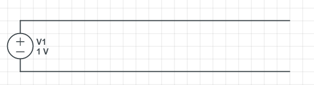
The source shows 1 Volt. if we hook a voltmeter anywhere between the top and bottom wires, we’ll get a 1V reading.
Change the voltage source to AC, and things start to happen.
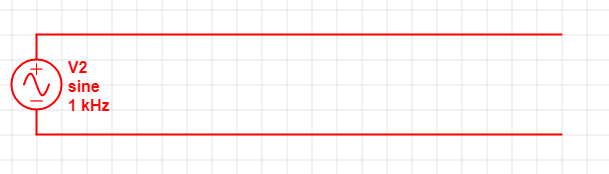
Even though we have an open circuit, the AC power source causes the ends of the wires to cycle between positive and negative charges. Even with nothing connected, there is measurable current in the wire and electromagnetic fields being generated around the wires.
This is why the power wires in your house can be traced behind a wall by an electrician using an electric field detection device. You can tell if a wire is live without touching it. This video shows non-contact voltage detectors electricians use to do this. They should be called non-contact AC voltage detectors. THIS DOES NOT WORK ON DC!
1.1 Transmission lines and antenna
For radio transmission to work, we need two apparently conflicting things to happen:
- Transmission line. We want little or no electromagnetic field emissions from the wire going from the radio to the antenna.
- Antenna. When we hit the antenna – which is really just another wire or set of wires – we want lots of electromagnetic waves to go out.
If we go back to our high-school physics and electricity class, we know that if we have an open circuit – like in our DC power supply diagram above – nothing happens. For power to flow, we need to close the circuit.
But in our AC power supply diagram, the circuit is open – and yet things are happening! We know this because we can detect electrical fields using non-contact voltage detectors.
With AC power, the circuit can be closed by electromagnetic waves between the wires. This simple concept is key to a lot of understanding about antennas.
For this beginner section, you’ll just need to accept the basic concepts. In the intermediate section we’ll provide links to some videos that will really help your understanding of what’s happening on the wires.
What’s happening in the transmission lines
If the wires are close together like in our illustration of the AC power supply, the two sides cycle between negative and positive charges because of the AC power supply.
The two wires generate electromagnetic fields, but they are opposite to each other as the power cycles (i.e. when one side is positive, the other is negative). The electromagnetic fields around the wires are opposite in polarity and cancel each other out. This is how twin-lead or ladder line works and why it’s called a balanced line.
In coaxial cables, the design of the wire with the central conductor and the braided wire around the dielectric material keeps the magnetic fields inside the cable.
What’s happening at the antenna
Forget about the theoretical isotropic antenna from the course material. Theoretical Point source. Pointless. The half-wave dipole is the real fundamental antenna, and pretty much everything else is derived from it.
The following gif image that we poached from this video nicely illustrates what’s happening.
At the start, we have two parallel wires coming off the AC power supply like in our initial illustration. They act as a nice transmission line, with the electromagnetic fields (focus on the white lines) nicely contained between the wires.
When we spread the wires apart, the fields are no longer confined between the wires and have to go through space to close the circuit. That’s a dipole antenna. That critical difference causes it to generate radio waves that go off into space.
When we’re dealing with a vertical antenna on a handheld radio, a magnetic mount car radio or an outside vertical antenna, the ground is one side of the dipole – as shown in the following gif from the same video.
Something really critical for these vertical antenna: the quality of the ground connection will dramatically affect the performance of the antenna.
In some areas, the conductivity of the local ground is terrible, and you have to add your own metal. You will also see this as radial metal rods around the base of a vertical antenna. This type of metal add-on is called a counterpoise, and effectively re-creates the other side of the dipole.
Counterpoise examples:
- The antenna-ground connection on a handheld ratio is lousy. It’s you, the meat-sack. This limits effectiveness of the radio. The typical short antenna on a handheld is referred to as a rubber duck. You can add a piece of wire sometimes referred to as a rat tail to create the counterpoise.
- On a magnetic-mount (mag-mount) antenna for your car, the car is the counterpoise!
- If you use a mag-mount antenna in your house or in a park to increase the range of your handheld or to operate a mobile radio, your transmission will be lousy unless you mount it on a significant metal surface to provide a counterpoise. Cookie sheets are a popular option.
1.2 Impedance and transmission
Impedance is measures in ohms, like resistance. But it’s not the same. Repeat after me:
- Impedance is not resistance.
- Impedance is not resistance.
- Impedance is not resistance.
- Impedance depends on signal frequency
- Impedance depends on signal frequency
- Impedance depends on signal frequency
Once again, the difference between AC and DC makes all the difference.
If you hook up some capacitors and inductors to a closed DC circuit, they charge up and then… they sit there looking dumb as a post.
In AC circuits, there is a constant cycle of charge and discharge for the capacitors and inductors, and this is where the magic of radio happens. It’s like they’re fighting each other.
- As the AC voltage rises, the capacitor and inductor charge up
- As the AC voltage drops, the capacitor and inductor fight the drop by releasing power back into the circuit
As frequency increases, the charges and discharge cycles get faster and faster, and it can get pretty freaky – and wonderfully useful.
In the right configuration of the right combination of capacitance and inductance, only a certain frequency will get through – and that’s how a radio is tuned to a frequency. In another combination, a frequency is blocked – and that’s a filter.
But what’s really important for transmission lines and antenna is that the impedance has to match up between the components.
For this beginner lesson, think of all the components in the chain – the radio itself, the cable to the antenna, the connectors at each end of the cable, any adapters between them – as a series of keyholes. The size of the keyholes and how well they line up is the impledance. Your radio signal needs to fly through the keyholes like Antman. (Go ahead and click. you need the break) If you don’t line it up just right… nothing gets through and power bounces back to your radio.
Impedance calculations are a little complicated, and are rated in ohms for a simple reason: ohms law. V = I x R. Or R = V / I.
It’s that V / I thing that’s important.
As the AC current and voltage cycle up and down in a circuit with capacitors and inductors, that voltage and current coming from the power supply is impeded by the charging and discharging of the capacitors and inductors. When you hook up your voltage source V, you can measure the effect by measuring the current flowing through the circuit, which will of course vary with the frequency because of the push-me, pull-you effect of the capacitors and inductors. When you measure V/I – looks like ohm’s law, doesn’t it? – for any frequency, you get the impedance for that frequency. You can calculate what it will be, but it’s a lot more complicated than it is for simple resistors.
1.3 Impedance and SWR
Our Ant Man video is amusing, but a poor analog of what’s really happening.
He’re a better example.
This apparatus is called a Newton’s cradle.
Think of the balls as the different components – the radio, the feed line, the connectors.
If they all have the same weight and size and string length, their impedance matches. You get perfect power transfer. Notice how the balls in the middle don’t move – all the power is being transferred to the next ball.
Here’s the catch with this animated gif: it’s like a radio with feed line and everything else required – but no antenna. So the last ball goes out, the power has nowhere to go, so it’s reflected back. There’s a measure you make of the voltage you send out versus what bounces back at you that’s called SWR – standing wave ratio. Ant Man had a really, really high SWR.
A perfectly matched antenna would be like a pillow with exactly the right density and softness to absorb the power of the last ball. Too soft, and the ball will go out a bit and swing back, still delivering some reflected power. Too hard, and the ball would bounce off of the pillow and send power back to the other balls. It’s never perfect – you always have some SWR.
That gif image above is computer generated. In the real world…
… it looks a lot more like this. It’s a cheap and imperfect unit, and you can see the power reflections causing all the balls to swing back and forth, and the power gradually dissipating. So there’s some SWR there.
Here are the key things to remember about SWR:
- Never operate your radio without an antenna or dummy load connected. All that power bouncing back is not good for your radio.
- HF radios will generally handle SWR up to 2 without a problem. If they have a built-in antenna tuner or you use an external antenna tuner you may still have limits on the SWR that can be handled.
1.3.1 Special case: SWR and VHF/UHF radios
You will generally hear from ham operators and most documentation that SWR doesn’t matter above 30 MHz – you don’t need an antenna tuner.
It’s not always true.
Antennas designed for the dominant VHF (2 meter) and UHF (70 cm) bands work well for both with low-enough SWR that you don’t worry about it.
Key exceptions that can generate lots of SWR include:
- Home-made antenna. You built it but you didn’t test it. SWR can be extremely high. Like with this thing. Always test the antenna before hooking up to your radio.
- Mag-mount or other vertical without counterpoise. Your vehicle, ground or some other metal thing is the counterpoise. Without the counterpoise, the SWR can be very high. Read what to do about that.
- Other VHF/UHF bands. Other bands in the VHF/UHF range are available. The 6 metre band is in the VHF range and has become increasingly popular for long-distance communication. Some mobile radios support it. These bands need different antennas than your 2m/70cm antenna.
1.4 Wait a minute – my radio handles multiple frequency bands! How can it have the same impedance across all of them if impedance is based on frequency?
Great question, Grasshopper! You are learning!
Within a given frequency band, the impedance on a cable and the components down the line will vary a bit from the lowest to the highest frequency in the range. The SWR generally varies, but not enough to fall out of the range the radio can handle.
When we jump between frequency bands, that’s where we have to watch out.
- On the radio: it doesn’t matter. The signal down the line is not influenced by the impedance of the signal generator. See reference at bottom of page in change section for 2021-02-15.
- On the cable and connectors: they are designed to have pretty consistent impedance across a wide frequency range – including, for the most part, the HF, VHF and UHF bands of amateur radio. Better connectors and cables will be rated for a wider frequency and power range.
- The antenna. This is where things get funky. There are antenna that are resonant or close for up to 3 or 4 frequency bands. If they can keep the SWR at 2 or below, you are good to go. If SWR goes higher, you need an antenna tuner to compensate. Newer antenna tuners are automatic. Only older stuff requires manual antenna tuning. Many large radios now have built-in antenna tuners. Older manual antenna tuners should be checked and adjusted for SWR each time you change frequency band. You generally don’t need to re-adjust within a frequency band – but you can for optimal performance.
1.5 Impedance, cable and connectors – in the real world.
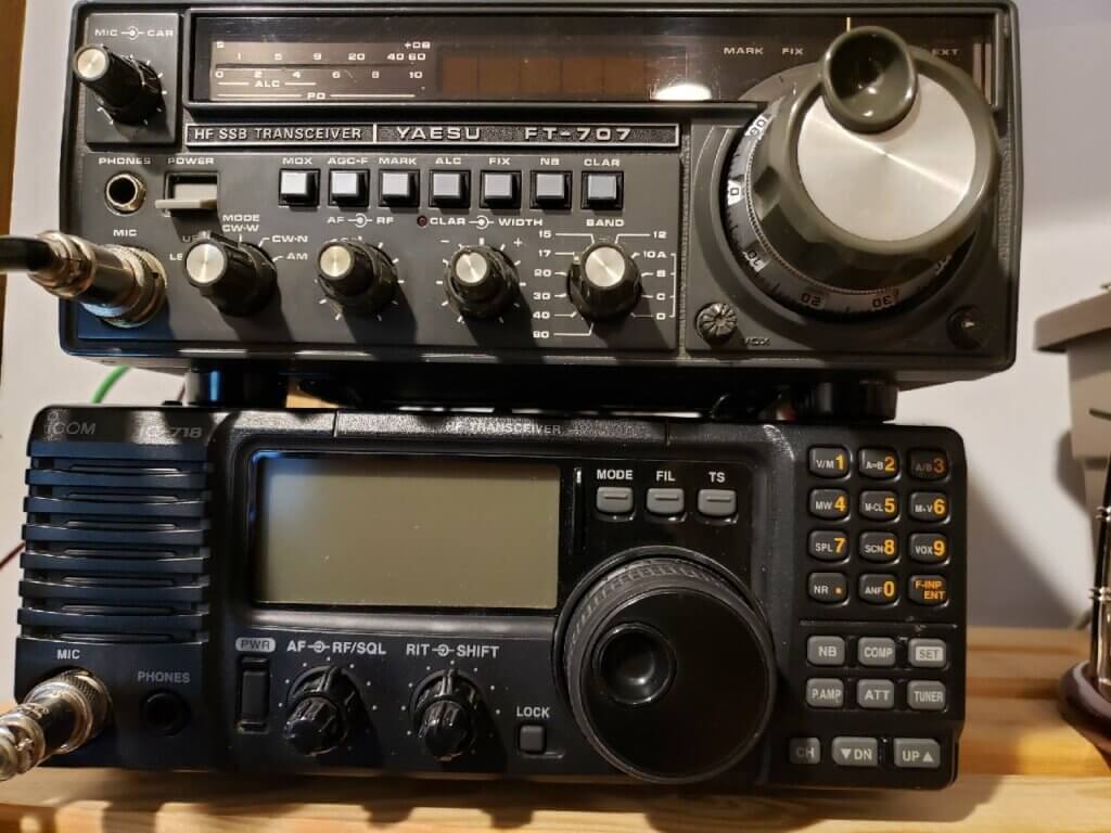
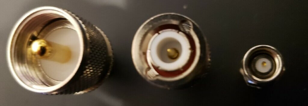
Other than SMA and SO-239/PL-259, the only other antenna/cable connector that might matter is BNC. Big radios have SO-239 connectors. Handhelds have SMA – but it might be male (Baofengs) or female (Yaesu). BNC is starting to appear on some radios. BNC is a nice compromise if you are making an antenna that might connect to both SMA on an HT or SO-239 on a bigger rig. It’s generally easier to crimp a BNC connector onto a cable than SMA or PL-259 and it’s less prone to detaching from the cable that an SMA connector. Adapters are easy to get, and it’s very fast connect and disconnect.
The following picture shows the three types of connectors. The labels are for the end of the connector closest to the center of the picture.
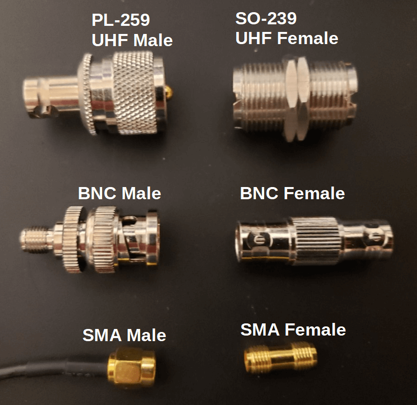
In ham-speak, you never refer to PL-259 or SO-239 as a UHF connector. We mention it this because many on-line suppliers do not hire ham operators to write their product descriptions. If you don’t find it, try searching for “UHF connector” instead.
There is some confusion on which end is male and which is female. The more observant may look and say… wait a minute… the female connector goes into the male connector??? That’s because…
The male connector is the one with the pin – as tiny as it may be. This is a family web site, so we’re not getting into further discussion of human anatomy and its functional parts.
Make sure any connectors and adapter you buy are 50 ohm impedance. This is generally not a problem for PL-259/SO-239 and SMA. You have to be more careful with BNC because they are sometimes used for cable TV coax which is 75ohm impedance.
Your radio’s antenna connector has co-ax (unbalanced) output – and as the source, it’s impedance doesn’t matter. It doesn’t matter if your radio has SMA, SO-239 or BNC. They are all designed for coax cable, so they are all balanced connectors.
The cable to your antenna and every thing else will be 50 ohm coax. You might get different diameters and specs for less resistance and more money, but it will be 50 ohm. It will most likely be RG58. If it’s anything else… that RG58 crimp-on connector you bought might not fit. Always figure out which cable you will be using before buying the connectors.
The odds are you won’t ever or use ladder line. You will only get into twin-lead/ladder line (balanced) if you start dealing with some big power radios and/or you get crazy about reducing line losses. Ladder line has impedance ranging from 300 to 600 ohm and will require a balun adapter right on the output of your radio. If you’re dealing with that kind of power, the adapter on the radio will be SO-239.
2.0 Intermediate level antenna, impedance and SWR
Remember how the best parts of high school classes were the labs and the movies? You don’t? Then you’re not a geek. And it’s a wonder how you got this far in this training material.
After reviewing way too many bad videos (tip: if it starts with equations, that’s a bad sign), we found that these really helped our understanding.
Some of these videos are pretty old – from the 1940s and 1950s – and feature animation and explanations that beat anything recent.
The videos inter-relate and reinforce each other. It’s hard to pick which one to watch first. It’s worth your time to watch them a second time not just to reinforce the learning, but because something from a later video may help you understand something from an earlier video.
If you think you’ve found a better video than these for explaining what’s happening, send us a comment.
2.1 Understanding SWR and impedance matching.
If you think think our Newton’s cradle analogy is cool… or if you think it’s absurdly wrong… HAVE WE GOT A VIDEO FOR YOU! (AT&T from 1959). This demo kicks our sorry butts around the block.
The guy doing the demo seems really pleased with himself – and he should be. It’s amazing for understanding SWR and mismatched impedances.
2.2 Transmission lines and antenna
The antenna gifs we used in the beginner section came from this US Air Force video. It does a brilliant job of showing you how AC current behaves in the transmission lines and the antenna.
This 1949 Royal Canadian Air Force animation producted by the National Film Board of Canada goes a step further, doing a better job of illustrating how current and voltage flow through the antenna. You can clearly see it’s a complete circuit. WARNING: the theme music may cause you to stand at attention and salute.
Take it a step further, and this modern animation and this one do a great job of showing how the movement of the electrons generate the electromagnetic waves that are emitted by the dipole. The best visualisation of how the radio waves launch from the wire starts at around 3:50 in the first video.
2.3 Balanced and unbalanced lines
Our favourite explanation of balanced and unbalanced cables is from IZ2UUF.
Really good stuff.
2.4 Bandwidth – for signal quality and for wider frequency range
We wrote a web page and did a video of it on the concepts of amateur radio bands and bandwidth. We show an RTL-SDR device that can monitor multiple signals at the same time.
How does wider bandwidth enable us to monitor multiple signals at the same time? Why is bandwidth important for signal quality? The Royal Canadian Air Force has another great explanation.
2.5 Signal Propagation
How does the signal bounce across the sky?
Old-school animation from the US Air Force on propagation.
For comparison, something more modern. https://www.rohde-schwarz.com/ca/knowledge-center/videos/understanding-hf-propagation-video-detailpage_251220-909312.html
3. Advanced Topics
This section is still in development. We’ll be adding more.
3.1 Experimenting with capacitors and inductors
For the geeks: I had trouble with the concept of impedance until I found an exercise from the University of St Andrews in Scotland – The RC Low-Pass Filter. The Prev an Next arrows at the bottom of the page will take you through more experiments.
3.2 Closing the loop: Kirchoff’s Law
In our beginner description of antenna and transmission lines, we talked about how an active circuit is a closed loop, and how in AC the loop can be closed by an electromagnetic connection.
At some level, understanding the different antenna types is helped by the understanding of Kirchoff’s law, where all the voltages in a circuit have to add up to zero. Think of it as what-goes-in-must-come-out. Awesome youtuber ElectroBoom gets into a great argument about it with a famous MIT nuclear physicist. Check out his thorough description of Kirchoff’s law (starts heavy, but gets into basic explanation at the two-minute mark), and you can check out how his argument with the physicist wraps up here.
Electroboom’s videos are educational and a little crazy – but he really knows his stuff and explains things extremely well.
3.3 University Lectures on Line
Professor Matt Anderson on ElectroMagnetic waves and he has a lot more
Change history for this page:
- 2021-02-15:
- Section 1.4 Corrected text on impedance of radio. “The standing wave ratio or position in a waveguide cannot be affected by the internal impedance of a radio“. Reference: Electronic Applications of the Smith Chart, Phillip H. Smith, p. 26, McGraw Hill 1969.
- Added section 1.3.1 for SWR on VHF/UHF radios