nanoCAD and Gweike Laser Cutter Update
We are updating our 2D CAD and laser cutting class materials because:
- Draftsight is no longer being offered for free. It’s a bargain for the price , but amateur maker space members are notoriously cheap.
- The laser cutter software has had a change in its behaviour. Nobody can explain why. Dunno if it’s the software or the machine. But it still works
- We learned a few things about errors and behaviour of the laser cutter software that we want to share.
nanoCAD 2D software: best free choice for 2D and laser cutting
Other products we looked at – and rejected
We looked at and tried several different products for 2D CAD to replace Draftsight.
We chose Draftsight originally because of its high level of AutoCAD compatibility. AutoCAD’s command-line interface is a de facto industry standard. It takes a little more effort to master, but it’s worth the effort. Your work becomes faster and more accurate.
Websites that compare 2D CAD products seem to be buitd to get clicks. They do a vague description of the products without a serious evaluation.
To save you the effort, here’s what we found when looking at different products specifically for 2D CAD and laser cutting.
- LibreCAD. Nice, completely free and open source. Nothing whatsoever to do with the LibreOffice suite of products. A little buggy and very little apparent development in the last 3 years. A common problem: not enough developers willing to do the work. It’s a crying shame, because the product looked really promising.
- FreeCAD. Awesome product for 3D CAD. Tons of tutorials. Extremely powerful. Active development community. But really designed for 3D and not the 2D that’s better suited for laser cutting. And it’s not the AutoCAD interface. If you are doing 3D design… wow. Well worth the effort. You can parameterise this thing to extremes, giving label/variable names to dimensions, and making other dimensions relative to those based on mathematical formula.
- QCAD: Worth a look, in full development with regular releases. Dramatically improved from 3 years ago. Command line capability is there, but different from AutoCAD in many ways. Now supports full Microsoft font set. Its free version is a feature-reduced version of Pro that only supports .dxf format and limits a lot of capabilities. Pro is available for CAD$50 one time fee with a year of free updates, and is probably worth it with supports for a bunch more formats (.dwg, .svg), can vectorize text and drawings. If you are not completely wed to the AutoCAD interface, pay the $50 and buy this one. It also has a CAM modules (extra cost, free trial) that can generate Gcode for CNC machines.
- AutoCAD Fusion 360. It’s a bit of a rigamarole, but it is downloadable for free. The problem: it’s a completely different product from the standard AutoCAD people know and love. Completely different interface. And like FreeCAD, not great for 2D. It’s a great product, but it gets a lot of hate because people expect the standard AutoCAD interface.
- nanoCAD: Best free compatibilty with AutoCAD. Has some 3D features that might be useful for CNC. But… free version seems to be falling behind the paid versions, and paid version is now annual subscription like DraftSight.
Bottom line for 2D CAD and laser cutting:
- If free and AutoCAD/DraftSight is critical, go with nanoCAD
- If you don’t care about AutoCAD interface compatibility and you want to do a lot of work with text and images and different formats, try QCAD. It’s worth the $50 to move up to pro, which is included as a free trial. You will easily save that in time and effort with the integrated text and image vectorization capabilities
- We need to look a little harder to see how well they work for CNC.
For the rest of this document, we are focused on nanoCAD.
nanoCAD: key features and versions
We’ve seen nanoCAD evolve over the last few years into a solid, reliable 2D CAD product with a high level of AutoCAD interface compatibility. It has a very active user community. There are tons of high-quality training videos on youtube. Download the program and click Help on the menu bar to get links to their youtube channel and support forums.
Like Draftsight in its old free-version days, there’s a free version and a pro version that you can get for an annual fee.
As of the time we’re writing this (April 2022), the free version is still available here but it is no longer following the releases of the commercial product. It’s stuck at version 5. The website says it’s an “older version of the software”.
nanoCAD vs AutoCAD differences – and advantages
Command line
Sure, there will be some nits on different commands, but it’s the same structure. Enter the command in the windows at the bottom of the screen, and it prompts you for the parameters to get the job done.
The better you are at the command line interface, the more you will notice the differences.
- No command line calculations. AutoCAD and Draftsight allow you to put in math instead of numbers. For example, if you want to scale something from 533 mm to 225 mm, you can enter the factor on the scale command as 225/533. With nanoCAD, you need to break out the calculator or spreadsheet.
- No negative dimensions. Use the mouse. So you’re drawing a 10X10 rectangle from origin (0,0). In AutoCAD and Draftsight, Where to you want the rectangle?Upper right quadrant (10×10)? Lower left quadrant (-10 X -10)? It’s all controlled by positive and negative values. With nanoCAD, it’s a 10X10, and you have to move the mouse to pick the quadrant. It’s a little easier for noobs, but aggravating to the AutoCAD pros.
icons and layout
They can’t plagiarise the entire interface. But everything is pretty much there. Just hover over the icons to get the descriptions.
file format: Direct DXF support!
AutoCAD and Draftsight expect you to open and save files in .dwg format. You need to run an export command (dxfexport – or was it exportdxf?) to get a .dxf file that’s compatible with the laser cutter.
nanoCAD opens and saves in either .dwg or .dxf format. No more remembering to “export”. Default is AutoCAD 2013 DXF compatible – perfect for our laser cutter and CNC machines.
when you start… no open file
Start the program, and it looks like you’re ready to start drawing.
Enter a command… and it’s rejected. Typo? Try again. Same error.
You need to File… Open or File… New first. You will be burned by this. Repeatedly.
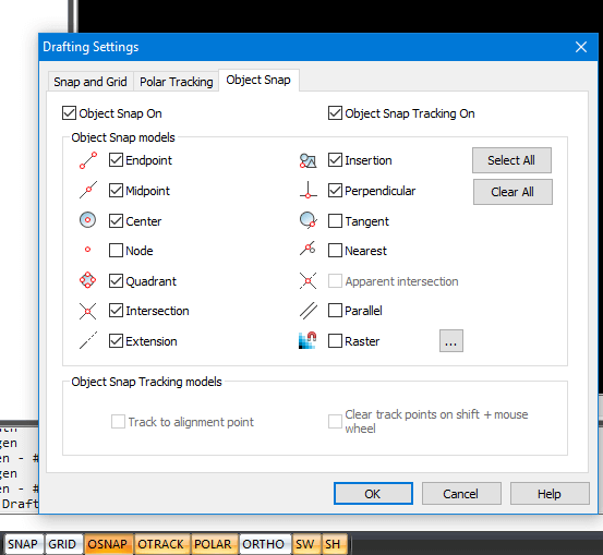
Object snap (OSNAP) works great. Use it.
Some people love the SNAP feature of CAD and drawing programs. If forces all your drawing to align with a visible or invisible grid. I really don’t understand those people. Probably the types who prefer corn syrup to genuine maple syrup on their pancakes.
So if you’re like me, make sure it’s off on the control panel on the bottom of the screen. If you want it on, you probably want to turn the GRID icon on as well to see where it’s going to force you.
Object SNAP (OSNAP), on the other hand, is phenomenally useful. It tries to tie you drawing to specific points – intersections, line ends, centres, etc. It saves a lot of trouble and time.
Right click on any of the buttons for the options. For OSNAP, don’t stop there – click on Drafting Settings at the bottom of the menu. This brings up a better menu of options and settings. It’s a rich feature set.
The other useful controls on the menu:
- ORTHO: forces your lines to vertical or horizontal (orthogonal) lines
- POLAR: like ORTHO, but allows you to specify angles. Like 45 degrees
- OTRACK: in addition to the OSNAP points, show more tentative drawing lines that link to the different POLAR angles and OSNAP points.
Won’t somebody think of the laser cutter?
A couple of things to consider in your drawing to make life easier when you import to the laser cutter.
Mind your origins
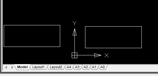
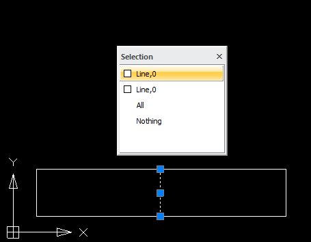
ucsicon: (0,0) origin is the same on the laser cutter. Bottom corner here is bottom corner on the laser cutter software.
Sooooooo many times, users bring up their drawing in the laser cutter software and see… nothing.
In the snapshot above, the rectangle on the right will show up on the grid. The one on the left will be off of the drawing grid. Too many times we’ve seen users with drawings waaaaaaay off the grid.
Mind your dimensions.
The grid for our laser cutter is an exact match of the cutting bed – 900 mm (3 feet) X by 600mm (2 feet) Y.
Check your dimensions before saving the file. Your scale might be way off.
Use the dimension lines.
- Great nanoCAD feature for dimensions: in AutoCAD, DraftSight and nanoCAD, the default font size on the dimensions is so small that it’s illegible. You can increase the size or maybe remember to look at the detail menu on the side… which is so detailed it’s hard to find.
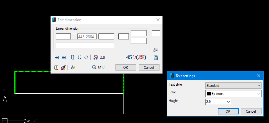
- With nanoCAD, right click on the dimension line and you get the Edit dimension box that shows you the dimension size (445.2664). In that same box, you can click on the Text Style icon (bottom row, third from left), and the Text Settings box appears to set the font size of your test to a legible value.
Mind your overlaps – and nanoCAD does it better.
We covered this in our CAD class – adjacent objects like rectangle may have overlapping lines. That’s bad when laser cutting or milling – it will slice the same area twice.
In nanoCAD, once you’ve exploded the objects, clicking on the overlapping line shows you that there are two elements, You can delete one or the other or both. Th
Text and images: go big and use external vectorization website.
A common problem when you load your project on the laser cutter: your text or image has disappeared.
- Free nanoCAD does not vectorize text or images for you
- THE LASER CUTTER IGNORES RAW TEXT AND IMAGES
- TEXT AND IMAGES NEED TO BE VECTORIZED BEFORE MOVING THEM TO THE LASER CUTTER.
For design, text and dimension calculations, you can use the text feature of nanoCAD. If you do this:
- Save the original design with a name like myfile_raw_text.dxf
- Once you’ve replace the text or drawing, save it as a separate name like myfile_vectorized.dxf
Text generated in a word processor look better than the rendering in the CAD program and has a lot more options – features and effect like circular text and others.
To vectorize your text or images:
- Make them big. Use your favourite word processpr and go to a big font – 28 point or above. Modern font resizing is more than just scaling – the letter can actually be different. The vectorization software appreciates the extra detail. We’ve seen smaller font sizes include intersecting lines that cause problems.
- Snapshot the text from your file – but make sure there are no artifacts like the cursor in the snapshot
- Convert it to .dxf on a site like convertio or vectorization.org
- Open or import the .dxf to a new tab
- Don’t see anything? Try zooming out. It probably comes in huge and off the current visible area of your drawing
- Scale it down to the size you need before copy/paste to your drawing using the scale command.
Do not use the colour red in your drawings
Many people make this mistake.
The laser cutter software will highlight any errors it finds by turning the offending shape/vectors into red.
Problem is… if your drawing is red, you can’t see the errors.
Avoid red or colours close to red.
Clean up artifacts
Any little bits lying around need to be cleaned up. Even a single pixel. They will all cause errors in the laser cutting software.
Engrave using a cut
Is a line drawing good enough?
- Use a lower power setting that doesn’t cut through the material.
- Be sure to use a separate colour from your cutting layer
- Order the “engrave” cut first
- We are working on a settings board
CNC: different from laser cutter. It likes solid areas
Special preview!
The laser cutter uses a raster process. Scanning line by line from the bottom to the top of the design, when it hits a line, it starts burning. When it hits the next line, it stops burning.
CNC is different. It likes to hollow out shapes. So we need to fill the shapes.
- Draw your shape
- Command line: HATCH
- Type: Custom
- Other predefined tab: SOLID
- Click icon beside Add: Select objects
- Box disappears, select objects to fill and hit enter
For a thicker object that’s not filled (like a thick circle):
- Use OFFSET to draw circle in a circle (as an example)
- Repeat process above, selecting both circles
- Or: (limited) adjust the Line Weight parameter of the object
View of fill and lineweight controlled by buttons at bottom
To add depth: adjust the thickness parameter of the object (NOT TESTED YET WITH CNC)
- Doesn’t show on 2D
- To view: View -> Visual Style -> 3D wireframe, the View -> Orbit to manipulate 3D view
- To return to 2D view: Views -> Plan View -> Current UCS
On to the laser cutter
It lost its mind. Absolute-ly. Immediate fix.
At some point in the last few months… we don’t know why… we tried all the settings… we tried rebooting…
… the laser cutter would no longer cut relative to where we set the laser head.
Everything is now based on absolute position on the grid.
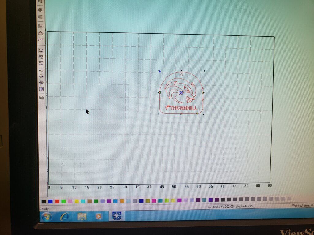
The full grid in the laser cutting software corresponds exactly to the cutting surface of your laser cutter – 90 cm wide by 60 cm high.
You need to ensure “Immediate” on the right side of the screen is no longer checked, or it won’t work.
Where your drawing is on the program’s grid is exactly where it will cut on the machine. Period.
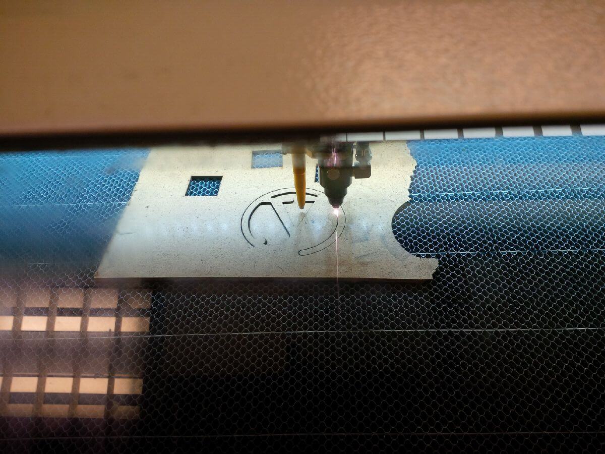
To griddle or not to griddle?
The cutting surface of the machine is the entire surface when the griddle is not present.
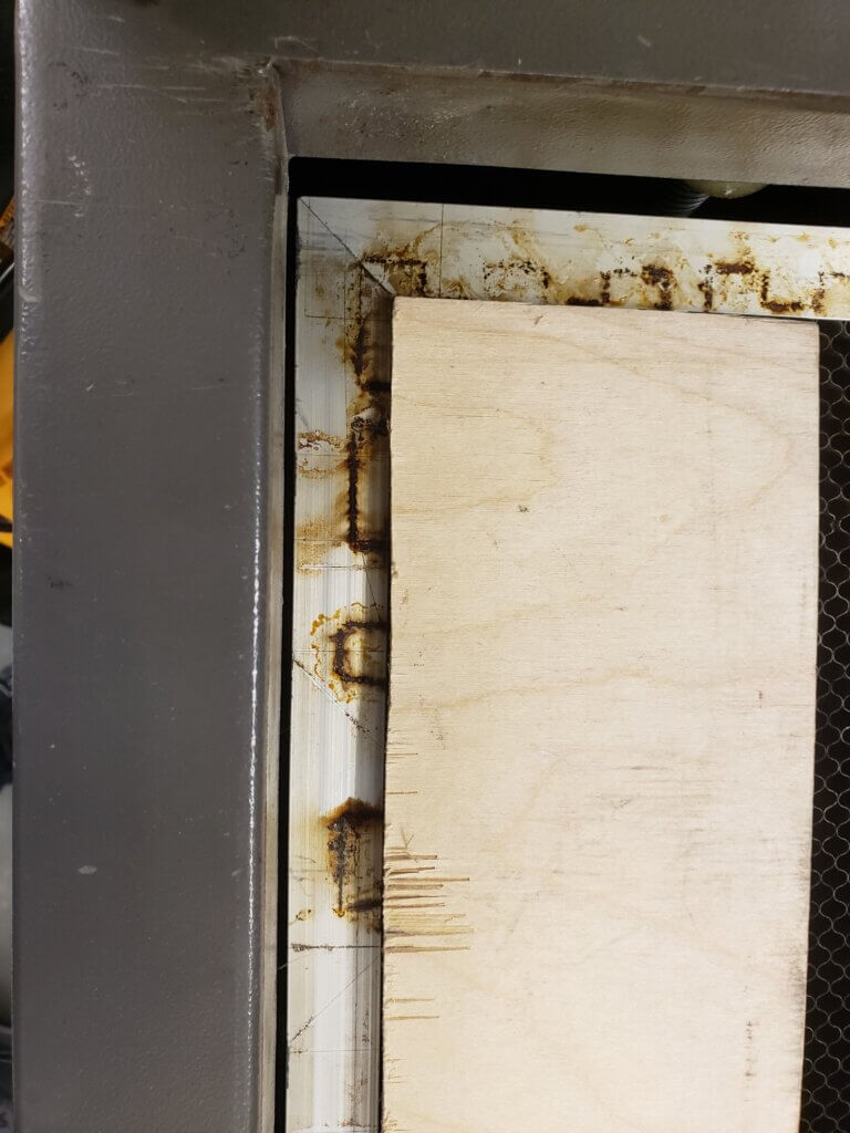
If you are using the griddle, your material is placed inside the border of the griddle, as in the image above. To cut up there, you need to move your drawing to the upper left corner of the grid on the screen… but not too close. You need to leave space for that griddle border.
Another option: test first, then place your material
If there is plenty of space for your material, load your design and run the Test first to locate the laser’s starting point. Then place your material based on the where the laser stopped.
Laser cutter Pause button is your friend
You started cutting, and something goes wrong – like a cut-out piece half falling in and half sticking out in a way that could interfere with laser head movement. Or someone needs your help. Or that bucket of cola from the burger joint wants out now and your job still has another 30 minutes.
Fear not. the Pause button will pause the cut. Take care of business, come back and resume.
Checking for errors
- Make sure original drawing is not red so you can see where the objects are
- Look for double little squares at the end of lines to identify crossed points and open shapes
- You might have to zoom WAY up to see them
- Tick only one box at a time to see errors by type
- Tiny artifacts can be spotted by looking for the little boxes
- You may be able to heal gaps by increasing gap fill size
- NEVER FREE-HAND LINE JOINS IN YOUR CAD. ALWAYS USE OSNAP.
TEST TEST TEST ON MATERIAL
We have found that material characteristics can vary from batch to batch, especially for MDF.
- Test a simple cut and engrave to see how it works on your material
- Adjust parameters as required
- Scale down your drawing and test on a smaller piece of material