Understanding ground. All of them.
Get the dirt on ground
Ground is a term that is thrown around far too loosely because it means different things. The dirt you’re standing on. The beef in your burger. The key ingredient of that stimulating beverage you picked up at at your favourite coffee shop. It’s important to understand all aspects of ground for operation of your radio and for the safety of your equipment, your home and you, the meat-sack.
This section is not part of our Canadian ham radio license training. It won’t hurt you to read and study it – it may even help. But as a best strategy for passing the test, we recommend you focus solely on the test training material. Once you get past that, come back and read this. The information here is far more practical.
This page covers the different types of ground and their importance. We won’t cover the detailed technical aspects of how to make the ground connections because (a) there are other great references out there that cover those details (b) it’s a very important safety issue and (c) we don’t want to get sued.
DISCLAIMER
CONSULT A PRO FOR THIS STUFF. ELECTRICITY AND RADIO WAVES ARE DANGEROUS AND CAN KILL YOU. WE ARE JUST PEOPLE WRITING A BLOG AND MIGHT BE COMPLETELY WRONG ON EVERYTHING.
BIG SAFETY WARNING
If you are using an outdoor antenna, disconnect it when not in use and when there is any chance whatsoever of lightning. Even if you have heavy duty outdoor grounding.
The best source we’ve found of information on antenna grounding is the ARRL’s Grounding page.
For amateur radio, there are four types of ground to consider:
- A zero volt reference point
- A general electrical safety thing – for some operating conditions and faults in your equipment
- An extreme electrical safety thing – for lightning
- A part of your antenna
With these all covered, we’ll deal with the issues common for all ground types.
- 5. Should all these grounds be connected?
- 6. Basic ground connection
- 7. Radio equipment power and ground connection
1.0 Ground as zero volt reference
Going back to theory… voltage is a difference in potential. But difference from what?
If you have a battery in a small device, it’s the difference between the positive and negative terminal. About 1.5 volts for a AA battery.
If you tie the negative terminal to a ground cable, and we consider the ground cable to be at zero volts, the difference between the the two terminals will still be 1.5 volts. But now I can tie other batteries and devices to the same ground cable, and that ground cable will be the 0 volt reference for everything.
But be careful: not all grounds are the same voltage. Sounds weird, but it’s true. If you drive two metal stakes in the ground at two different places, and hook a voltmeter between the two points, you might read a voltage. This is a problem in large buildings or campuses of multiple buildings. This is an example – and it can be serious. Broadcast and telecom facilities are very sensitive to this, and can spend a lot of money establishing a single ground point for the building. They need to link all the equipment racks with large copper bars, plates and cables to the single ground point for the building or even multiple buildings.
So all that radio equipment – the transceiver, antenna tuner, amplifier, and whatever else you have needs to be connected to a good common ground.
We also want the ground to be clean and stable. That 3rd prong in your electrical outlet? Radio equipment avoids it because it can be noisy. All those ground wires running through your house are all connected together, and they are picking up electrical noise from all the devices in your house. And don’t forget that any wire hanging out there is an antenna. Those ground wires are picking up all kinds of signals.
How bad is it?
If we plug in an Arduino board, dont hook up anything to it, and read the voltage on one of the pins… we read a voltage and a very messy signal.
That’s all from ambient electrical and radio fields from a wire that’s a fraction of a centimeter long
If you measure the waviness of the signal, you will see that it generally goes up and down 60 times a second. Does that sound familiar? It should. Our North American electrical grid is 120 volts AC at 60 cycles per second. That raggedy wave is all from the electrical fields floating a around the house. If we want ground to be a good zero volt reference, all that electrical noise is a bad thing.
2. Ground for electrical safety.
First the good news: if you’ve wired your ground like we suggested (after consulting a pro!), you are covered for safety.
If there is an electrical fault in any of your equipment, you run the risk of the power connecting to the chassis (sometimes called “grounding out”). Radio chassis are always metal because they need to block any RF signals coming from the internal components. All those coils/inductors love to spit out RF.
A properly operating radio can send power to the chassis. If you are hooked up to an antenna that’s generating a high SWR level, a lot of power is flowing back into the radio and needs somewhere to go. That somewhere is the chassis, and the chassis expects to be connected to ground. If you didn’t ground the chassis, that somewhere the radio wants to send the power to could end up being you, the meat-sack, whenever you have the misfortune of touching the metal chassis. Newer radios try to protect you from this with a plastic bezel – but that’s only on the front. The sides, top and back are metal. Older radios have a nice metal front. The knobs are plastic, so you’re OK… until your finger slides over and touches the chassis. The shock from high SWR will feel like sticking your finger in a 120V socket – or worse because of the high current. Don’t ask how we found out. Just trust us on that one.
3. Ground for lightning.
If you have an antenna tower or any outdoor antenna, you need serious grounding with lots of metal in the ground to dissipate the power from the strike. Again, consult a pro for this
You may try to get away without grounding for an outside antenna. Many people do with various excuses – it’s lower than the building, other taller stuff around, etc. Bad idea. But if you do… disconnect your antenna when your radio is not in use or if there’s any chance of lightning.
We can’t stress this enough. If Ben Franklin had a bunch of electronic equipment in his house when he invented the lightning rod, he might have thought the thing was useless. A well-designed lightning rod/grounding system will dissipate the power enough to prevents fires, explosions and meltdowns, but there will still be enough power flowing to damage electronic equipment. In our neighborhood several years ago, a single lightning strike that hit just the right point on the electrical grid damaged VCRs, cordless phones and other equipment in houses that were as far a kilometer away.
ARRL has extensive articles on lightning protection.
4. Ground as vertical antenna counterpoise – a.k.a. RF ground
Vertical antenna are often one-side of a di-pole antenna, with the other side of the dipole provided by the ground. Really.
Our antenna page has more on this, or you can cut over to our favourite video on the topic.
5. Can all these grounds be common and connected?
Yes, and they should be. That can also include connecting to the grounding point of your electrical service entry. Local building and electrical code and/or a pro should be consulted. This article from ARRL has some good illustrations, and even talks about having multiple towers:
“If you are fortunate enough to have multiple towers, each
should have its own ground system of radials and ground rods.
If the towers are within 100 feet of each other, a radial should
be used to interconnect the towers“
Serious stuff.
When using a tower with a coaxial cable to the antenna, the references list a requirement to ground the coax to the tower at the top and the bottom… and every 75 feet if your tower is over 150 feet in height.
Multiple towers… towers about 150 feet in height… yeah, there are some maniacs out there.
6. Basic grounding points – if you’re not worried about lightning
So for whatever reason, you judge your system to be safe from lightning and want some simple grounding. Maybe your antenna is inside your roof or something you are hanging out the window of on the side of your house. Maybe it’s your rain gutter (that’s not a joke). Fine. Contact us so you can list us as beneficiary on your insurance and in your will.
But realistically…
The most basic ground is a connection to a copper water pipe in your house. Make sure it’s copper all the way to the water line coming into the house. Residential construction is increasingly using different types of plastic pipe, and that’s useless for ground. You can buy grounding clamps to connect a wire to copper water pipes at most hardware stores.
You can also drive a metal stake into the ground, or even better, a grounding plate (search for “earthing plate” on most websites). Here’s an example. It’s bigger than it looks. Check out the weight – 10 lbs.
So you’ve got a ground point… time to start hooking up the radios.
7. Radio equipment power and ground connection.
Look at the power supply for your radio – because the vast majority of radios have external power supplies. The power supply has a standard three-prong power cord, one of which is ground.
But the connection to the radio only has two wires, usually delivering about 13.8 volts DC, but as low as 12 volts. (Why 13.8 volts?) There is no ground wire going between your power supply and your radio because that would be the noisy ground from your house.
This is one of the reasons the radio power supplies are fairly large and heavy. Their circuitry is designed to give your radio the cleanest power. If they shared their ground with you, you would be getting all that noise on the house’s ground wiring into your radio. So our power supply is grounded with its power cord, but not sharing the ground with your radio.
Now look at the back of the radio. There’s a separate connector for ground. That connector is tied directly to the chassis – the metal case – of your radio.
That should be tied to a reliable ground source that’s separate from the electrical wiring for your home.
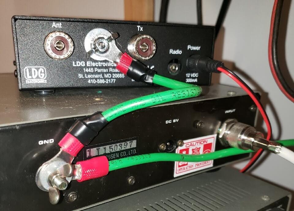
In the picture above, we’ve daisy-chained the copper ground wires between the pieces of equipment. Ideally, these would each go down to a common piece of copper, which in turn is connected to your ground point. The wire should be be thicker gauge. You can buy some nice 8-gauge wire with nice green (GReen = GRound) at most hardware stores.
7.1 VHF/UHF Radios
There’s an oft-repeated rule that you don’t worry about SWR above 30 MHz – i.e. in the UHF ranges. It’s not always true. We deal with this on our antenna page.
If you have a proper antenna, you can get away without grounding. But to be safe – like, say, if you’re creating your own antenna or have other gear kind of linked – you should consider the following.
7.1.1 Grounding point on mobile radios
If you are using mobile (think: car stereo size) radio, it should also be grounded – but you won’t find a ground screw like the bigger radios. In a car, the negative side of the power lead is connected directly (better) or indirectly to the car’s metal chassis. The chassis is the ground and zero volt reference for the car’s electrical system. Look at the wire from the negative terminal of your car’s battery – it’s connected straight to the car chassis.
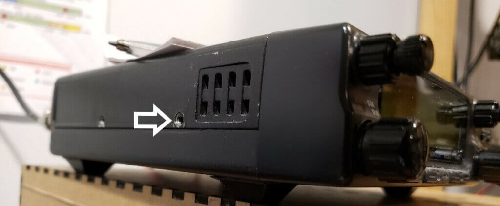
When using the mobile radio in your home or ham shack, it’s a good idea to also ground the chassis. Mobile radios usually have mounting holes in the side like in the picture above. That’s a good place to connect a ground wire.
7.1.2 No grounding point on handhelds
HT (handheld transceiver) radios don’t require grounding for one simple reason: they are entirely encased in plastic. There is no metal contact point to zap you. And their power is limited.
Take a look at power tools and a lot of small home appliances: most are fully encased in plastic, and, for that reason, can use a 2-prong power cord with no ground connection. If you are of a certain age when the first plastic-cased power tools came out, they were all labeled double insulated to justify not having the grounding connection on the power plug.
Image sources:
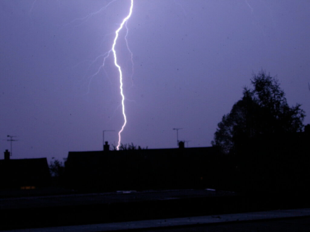
- Lightning: Photo by Steve Day from FreeImages
- Ground coffee: Photo by Eziquel (zick) Boita from FreeImages